Raspberry PI Based Weather Station
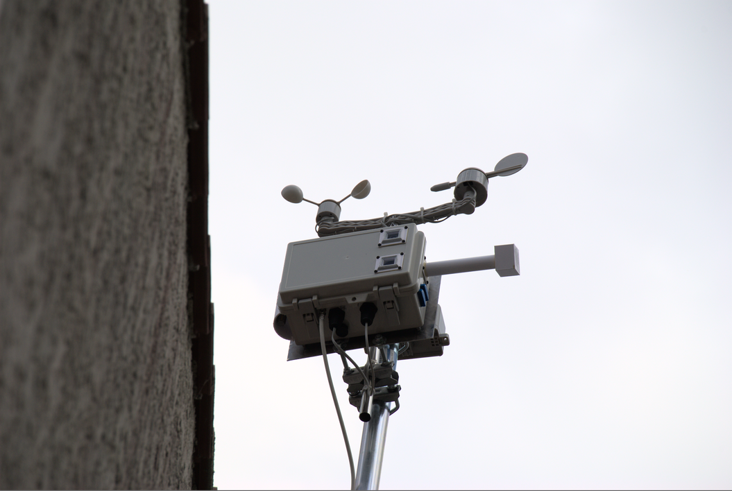
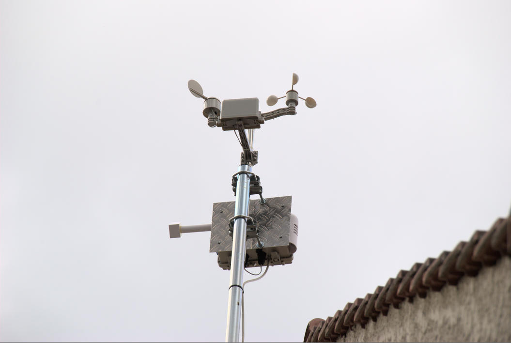
The Station is mounted on the roof-top, about 10m above ground.
I had to abandon using Solar power as the region barely provides enough solar energy in Winter to power the Raspberry PI inside for 2 hours. Even doubling the panel to 16W Total would not help. Reason I used the old Antenna installation and power the stations through the existing Coax TV Cable. Note that on roughly 20m length, the voltage drop is around 2V (which honestly is huge). I have to power the installation at my basement with 7.15V to have a stable non crashing Weather station.
So the below blog stays with the Solar array documentation etc. as it could help others for the sizing and more. However the current setup has had all solar-equipement stripped out.
Ordered Hardware
- SkyWeather - Raspberry PIU based Weather Station Kit for the Cloud
- Skyweather Lightning Pylon, Air quality Housing and Quarz Window Frames/Base sets
- Raspberry PI Zero W (Amazon).
- Amazon: PENG USB Femelle Prise Prise Adaptateur de Montage sur Panneau connecteur étanche
- Amazon: Aexit Couvercle de joint de boitier de jonction étanche 240mmx170mmx120mm avec cadre
- Amazon: 2 BQLZR RJ45 Jack vers Jack Interface M20 Ethernet/LAN en Nylon AP Panel Mount connecteur étanche IP68
- EBay - 3x Double Side Polished JGS1 Fused Silica Quartz Glass Sheets Plate 30x 30 x 1mm
- Sourcingmaps 10 pcs 5.5 Mmx2.1 mm male Plug DC Power Jack
- HSeaMall adapter connector jack female
- Transformer AC-DC (120-240V / 12V) 0.83W
- Power Buck - DC-DC Convert 12V / 5V 3A
Differences to the official project
- The OS running on the Raspberry PI will be based the Raspbian light. All deails to get all software running correctly are in the Software Installation chapter.
- The Raspberry PI Zero W is used. It drains a little bit more power (average 210mA with very short peaks at around 600mA) than the no W version, however using a USB WIFi Stick would draw more power even than that. Also - the builtin WiFi is well supported.
- The system being run in Europe, we will not be using the "English/Imperial system" but the Metric system for all units (Honestly, the English Imperial system is causing more trouble and is barely used by 7 countries on this planet).
- As I have long experience with Raspberry PI's and the usual SD-Card wearing, I decided to use a different approach to store the collected data. The OS will take advantage of Ram-Filesystems whenever possible to reduce the number of write onto the card. All regular data will be stored off-site. in this case, as the Weather Station is running at Home (roof of my house), and the PI Board has built-in WiFi, I modified the scripts to actually store the data on my Server's mysql Database.
- I'll write my own UI to display my weather data. Eventually, I'll also send it to Weather Underground if they want it.
- Using a 12V power supply to power the Weather Station. A DC/DC converter inside the power station will make sure 5V really each the Weather station.
The long cable causes a too high power loss (around 80m / 1.2V - probably an old cable, but that's what is there) which is not compensated by regular power supplies.
Replacement parts
- Air Quality Monitoring PPD42NS Grove Dust Sensor
Abandonned due to Solar Array not providing enough power - even while doubling the panel surface
- SkyWeather Solar Extender Kit
- Using a 5.6v Zener Diode 10W to limit the power output from the Solar Array to the SunControl board. It has proven that without the Zener Diode, the Suncontrol board was cutting power as soon as the temperature/voltage was too high.
- Battery Li-Ion NX 1S3P ICR18650-26J + PCM (28Wh) UN38.3 3.6V 7.8Ah Battery Specification
The used Battery is a 7.8Ah model. So we'll have a batter margin for sun darkness.
Preparing the Raspberry PI Zero W / Software side
Performed a minimal Raspbian installation on the Raspberry PI Zero W by following instructions of the Cleanup the Raspberry PI OS: Raspbian guide.
Optional components.
Not yet known if this will be required, but for documentation purposes:
SkyWeather Adding a fan Tutorial
Software installation
Pre-required packages as provided by raspbian.
~# sudo apt update && sudo apt dist-upgrade && sudo apt install git python-smbus python-setuptools python-pip libi2c-dev pigpio python-numpy python-matplotlib python-mpltoolkits.basemap build-essential python-mysqldb mariadb-server mariadb-client python-pigpio python-requests python-apscheduler python-futures python-funcsigs python-picamera fonts-freefont-ttf
Some other packages need to be downloaded from the required sources:
~# cd ~
~# git clone https://github.com/switchdoclabs/SDL_Pi_SkyWeather.git
~# git clone https://github.com/adafruit/Adafruit_Python_GPIO.git
~# cd Adafruit_Python_GPIO
~# sudo python setup.py install
~# SDL_Pi_SkyWeather/Adafruit_Python_SSD1306
~# sudo python setup.py install
Activate the required module
Note that the missing bits are that the i2c, GPIO and camera drivers are not activated by default. So start raspi-config, go to Interface options and activate all 3:
- P1 Camera
- P5 I2C
- P8 Remote GPIO
reboot the PI and you're done.
Configure root access for MySQL
By default, mysql-user will not have a password set, not even for the root-user.
Execute mysql_secure_installation to do the job for you, and follow the instructions.
~# sudo mysql_secure_installation
Once that is done, create the required Database for the SkyWeather system
~# mysql -u root -p
MariaDB [(none)]> create database SkyWeather;
Query OK, 1 row affected (0.003 sec)
MariaDB [(none)]> quit
Bye
~# mysql -u root -p SkyWeather < ./SkyWeatherSQL/WeatherPiStructure.sql
Enter password:
Now you'll be able to use the DB.
Some fine-tuning
When the PI reboots, it tends to loose time. If it is offline for a long time, even the external real-time clock won't be able to keep the time correctly. Hence - let's add ntpdate to the rc.local to load the time correctly.
Add the below lines of code to /etc/rc.local
# Setting system time (after a reboot)
systemctl stop ntp
ntpdate [NTP Date server IP or Hostname (FQDN)]
systemctl start ntp
This will make sure the time is always set before starting the weather PI software.
To reduce the write operations of the PI, we have already reduce the write operations to Disk by shifting all writes to a ram-disk, and syncing once every 3 hours the data to the SD-Card in one write operation.
One other trick is to make sure the SkyWeather.py software runs smooth. Then redirect all regular output to /dev/null, and all error messages to a log-file. Do this with in replacing the startup entry in /etc/rc.local with:
#1 Weatherpi running here
pigpiod
cd /home/pi/SDL_Pi_SkyWeather

# We send regular output to /dev/null, and errors to the actual Log-file.
nohup python SkyWeather.py >/dev/null 2> /var/tmp/log/nohup_errors.log &
The /var/tmp/log/nohup_errors.log will be moved to /var/log every 3 hours, or upon regular reboot.
Power usage adaptations
The raspbian OS performs various tasks controlled through the crontab. Of course, we want to execute these tasks when the SUN helps us at its max, so we'll move the cronjobs from early-morning/midnight to happen at plain mid-day.
Change the /etc/crontab to:
# Example of job definition:
# .---------------- minute (0 - 59)
# |  .------------- hour (0 - 23)
# |  |  .---------- day of month (1 - 31)
# |  |  |  .------- month (1 - 12) OR jan,feb,mar,apr ...
# |  |  |  |  .---- day of week (0 - 6) (Sunday=0 or 7) OR sun,mon,tue,wed,thu,fri,sat
# |  |  |  |  |
# *  *  *  *  * user-name command to be executed
17 *    * * *   root    cd / && run-parts --report /etc/cron.hourly
25 12   * * *   root    test -x /usr/sbin/anacron || ( cd / && run-parts --report /etc/cron.daily )
47 12   * * 7   root    test -x /usr/sbin/anacron || ( cd / && run-parts --report /etc/cron.weekly )
52 12   1 * *   root    test -x /usr/sbin/anacron || ( cd / && run-parts --report /etc/cron.monthly )
Hardware - test the setup
This is to test the electronics, all sensors are working etc. Once completed, go over to the Software testing chapter of the official documentation Skyweather initial testing. This will confirm that all components work as expected, and the PI is able to recognize all connected sensors.
I2C Connections
GPIO Connections
RJ45 Connectors
Connect the RJ45 cables from the Anemometer and from the Rain Bucket into their respective sockets on the PI Weather Board.
Connecting the Solar panels
For the inclination of the Solar panels, The latitude will play a role, and depending on the Season, Optimal inclination will be different.
A good source for calculating the inclination can be found here: Solar Angle Calculator
For my latitude, it would be in Winter: 18° angle, Spring/Autumn 41° angle and Summer 64° angle.
Note: The pictures linked to the connection-tables below are with courtesy of https://shop.switchdoc.com/.
The way it is built and implanted into the box after the successful connection testing.
Preliminary sensor report:
The following shows when running the weather collector program
SkyWeather Weather Station Version 055 - SwitchDoc Labs


Program Started at:2020-01-20 10:31:51

----------------------
I2C Mux - TCA9545:              Present
BME680:                 Present
BMP280:                 Not Present
SkyCam:                 Present
DS3231:                 Not Present
HDC1080:                Not Present
SHT30:                  Not Present
AM2315:                 Present
ADS1015:                Present
ADS1115:                Not Present
AS3935:                 Present
OLED:                   Not Present
SunAirPlus/SunControl:                  Present
SolarMAX:               Not Present
SI1145 Sun Sensor:              Not Present
TSL2591 Sun Sensor:             Present
DustSensor:             Present
WXLink:                 Not Present
Dual SolarMAX/WXLink:                   Not Present

UseBlynk:               Not Present
UseMySQL:               Present
Check WLAN:             Present
WeatherUnderground:             Not Present
UseWeatherStem:                 Not Present
The Raw data values written into the DB will show like this.
For the PowerSystem table:
batteryVoltage: V
batteryCurrent: mA
solarVoltage: V
solarCurrent: mA
loadVoltage: V
loadCurrent: mA
batteryPower: W
solarPower: W
loadPower: W
batteryCharge: %
For the Sunlight Table:
Visible: Lux
IR: Lux
UV: N/A
UVIndex: N/A
For the WeatherData Table:
as3935LightningCount: Counter
as3935LastInterrupt:
as3935LastDistance:
as3935LastStatus:
currentWindSpeed: Kph
currentWindGust: Kph
currentWindDirection: °
currentWindDirectionVoltage: ?
totalRain: mm
bmp180Temperature: °C
bmp180Pressure: hPa / milli bars
bmp180Altitude: m
bmp180SeaLevel: hPa / milli bars
outsideTemperature: °C
outsideHumidity: %
insideTemperature: °C
insideHumidity: %
AQI: µg/m³
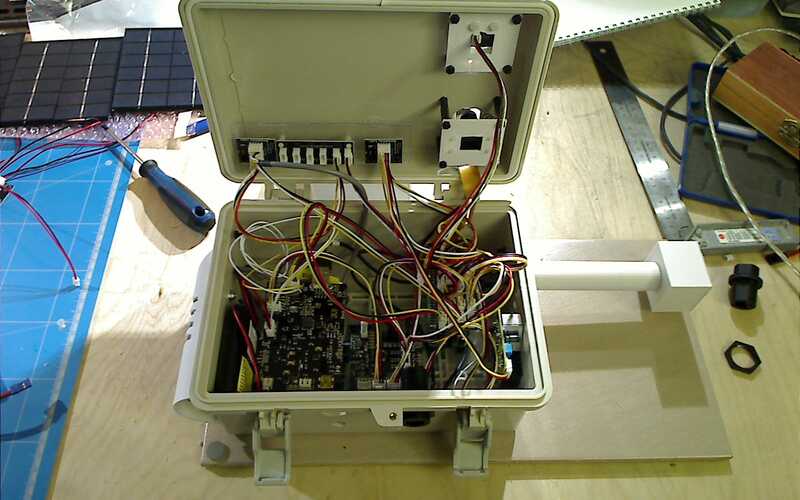
Putting it all in the box
as the box I got is way smaller than the one anticipated by SwitchDoc Labs, I had to trick a little with space.
In fact, it can hold everything even though I got some cable length wrong. Should not have followed the instructions to the letter while cabling it the first time.
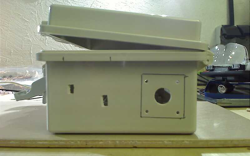
So - for the openings:
Camera and Light Sensor mounts
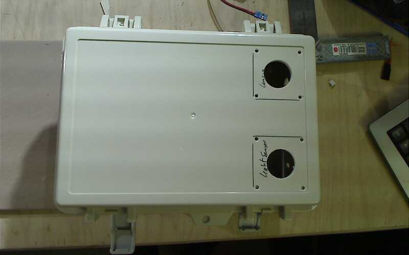
Holes for temp and humidity Sensor
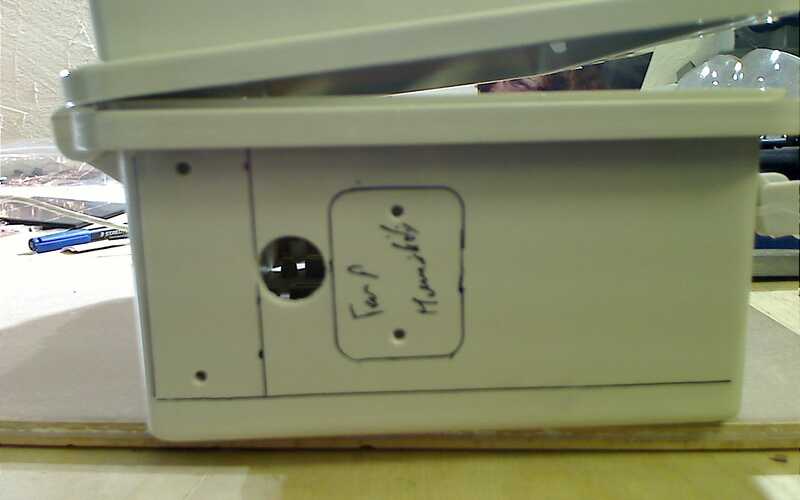
Holes for RJ11 plugs
Note that I did add a 3rd hole for the Solar-Panel power cable.
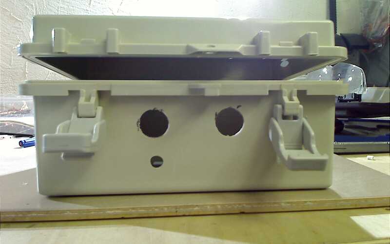
Holes for AQI sensor
This one will be mounted inside of the box. As it needs a certain position so the internal resistor can heat up the air and cause a air-flow for the measurement period.
Burn-In (Software)
For the Burn-in and Fine-Tuning Period, the system is in my basement. Also, as in Winter it can get quite cold and dark, I am unsure if the Solar-Array and Battery will be able to cope with the energy demand required by the entire weather station. For this, I decided to add a external jack/connector to connect an external 5V power supply. From my RC_Planes, I have plenty of step-up/down converters available, so I can hook up a LiPo battery and plug it in for enough time to power-charge the built-in battery of the Weather station.
This is how it looks like, and how I connected it to the PowerBoard mini-USB port.
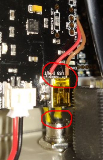
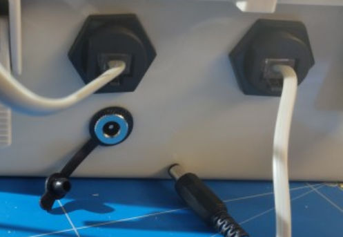
The connection layout given to me by a member of the switchdoc-labs forum: mini-USB connector pinout
The charge-cable is currently just a long USB Cable where I soldered the red and black wires to the jack plug, so it charges the Weatherstation battery pack.
Solar Panels
it took me a while to actually think about how to fix the actual solar panels on a back-plate, and how to weather proof these.
In the end, it was quite simple. What I needed was 2 things:
- A glue that does allow the thermal dilation of different materials and remains flexible over time
- A glue that is UV resistent
Having had some experience over time with normal Silicon glue, I opted for the Sikaflex 521 UV (You can find some on Amazon).
It is used by most RV drivers in europe to glue their solar-panels on the roofs of their trucks. If that holds, it definitely is good enough for my usage!
So - after preparing the aluminium plate to be held by the fixations, I glued it all together:
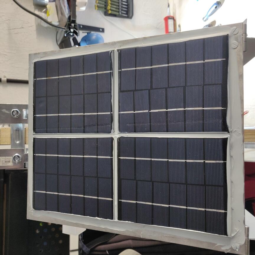
and made sure I had a waterproof box to receive all cables. Of course, all water-profing was done with the Sikaflex 521 UV glue.
The back-Side looking like this:

Air Quality Sensor
The air Quality Sensor intake posed a different challenge. In fact, it sucks in Air, and measures it through laser interference to look for particles in the air that go through.
As the holes are placed on the side and not under the entire box, I used two plastic bottle caps glued on with Epoxy to prevent rain from getting in.
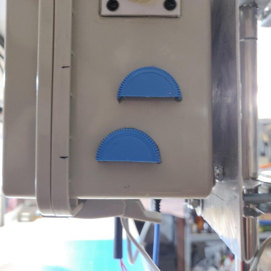
That should be sufficient to prevent any water from coming in. I don't think rain will fall in from below ;)
Will need to check the details and adapt the graphs according to: https://waqi.info/
Graphing and data collection
after having tested 3 different ways to collect the data to perform my graphs and display weather data, I concluded that using mrtg/rrd-type DB or prometheus is too restrictive.
Here is what I have tested so far:
- MRTG: Write data down into rrd-storage. Has the limitation that you can't store the CHAR type variable (lightning data last info), and will aggregate the data down to its own values/averages. The big advantage is that the DB will never grow larger than is required. Graphing with grafana requires some workarounds to display the data correctly (rain-data is always a pain).
- Prometheus: Has the same issues as MRTG data-source. Problem being that it will also aggregate the data as it wants it to be stored. Issues with grafana show up again when trying to display simple things like VARCHAR type data, or not have the values averaged according to time-interval.
- Mysql: The weatherpi software supports write directly into the MYSQL database. Using the builtin functionality however caused weird errors showing up in python when the network=link was not clean. Sometimes the software simply crashed.
The best method has been to actually modify the weatherpi software in such a way to dump the data to a text-format file, and let that file be served by lighthttpd.
Httpd protocol is best suited for handling data over the network, and if an error occurs, well, there is an error and that's it. No crash, no weird behavior, no nothing.
This has resulte me adding 2 putput format to the weatherpi software:
- csv-data. This data is used by my website to display the current data. It is the smallest in volume and is generated every 60seconds. See the results here https://www.solsys.org/mod.php?mod=weather
The data itself looks like this: 2.5146;59;0;1;Spurious Interrupt;1.5199335789;9.67663898073;2.5146;17.22;1009.15;120.0;1023.62762231;15.9;93.4;135.0;0.932625;17.22;68.976;3307.9008;741;0;0.0;449;
- sql-format. This is a simple sql-format inset string I can then use on my server side to write the data into the database. The data is polled every 5 minutes and inserted into the database.
The format is plain SQL and an output looks like this:
weather_datetime="1631522439",weather_rain=2.5146,weather_as3935_Lightning_Count=59,weather_as3935_Last_Interrupt=0,weather_as3935_Last_Distance=1,weather_as3935_Last_Status="Spurious Interrupt",weather_current_Wind_Speed=2.63988798075,weather_current_Wind_Gust=11.2617368414,weather_bmp180_Temperature=17.27,weather_bmp180_Pressure=1009.16,weather_bmp180_Altitude=120.0,weather_bmp180_Sea_Level=1023.63776577,weather_outside_Temperature=15.9,weather_outside_Humidity=93.7,weather_current_Wind_Direction=135.0,weather_current_Wind_Direction_Voltage=0.9324375,weather_HTU_temperature=17.27,weather_HTU_humidity=68.955,weather_Visible_light=3371.5488,weather_Sun_light_IR=751, weather_Sun_light_UV=0, weather_Sun_light_UV_Index=0.0, weather_Outdoor_AirQuality_Sensor_Value=449
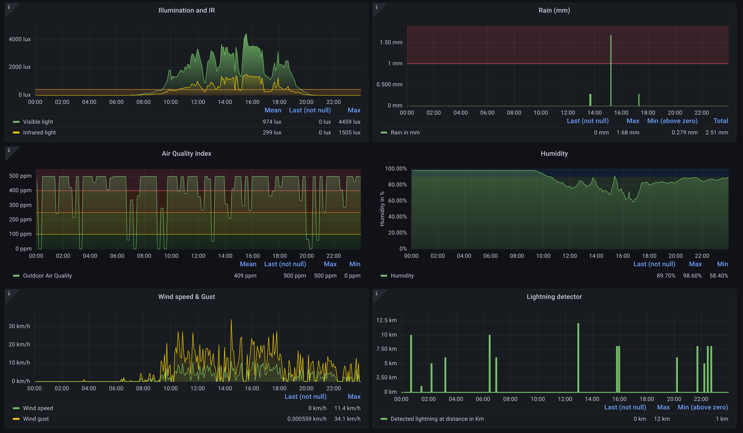
This data-snippet can be inserted very easily into the dedicated mysql database and processed directly by grafana. See for yourself:
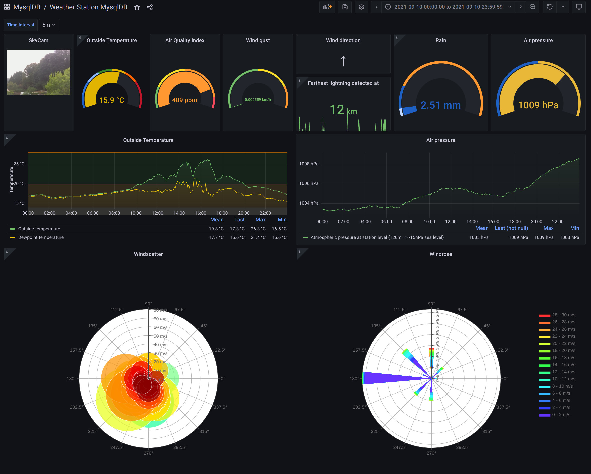
|